

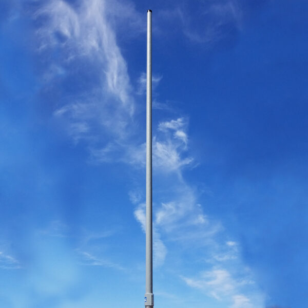
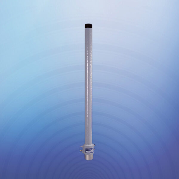
GS-2/3/4 ILS Glide Slope Antenna Array 328-336 MHz
Frequency Range: 328-336 MHz
Gain: 10 dBi
VSWR: 1.2:1 max
Polarization: Horizontal
Model Number: GS-2/3/4
Part Number(s): 1000-0579-202, 1000-0582-502, 1500-0149-203, 1000-0579-203, 1000-0579-204
NSN: 5985-01-048-0147
Request a QuoteAll Inquiries welcome
Applications:
Glide Slope Antennas are used to provide vertical guidance to aircraft during approach and landing of an aircraft under instrument fight rules.
Features:
The Glides Slope Antennas are designed to withstand 100 mph wind, 1⁄2-inch radial ice, temperature range of -50oC to 70°C, and 100% humidity. All elements are equipped with de-icing heaters and thermostats.
Characteristics:
Glide Slope Antennas operate on a frequency of 328 to 336 MHz on a nominal impedance of 50 Ohms and power up to 50 watts. A null reference glide slope antenna system is fed by two transmitters, one on the carrier frequency and the other on sideband frequency. A capture effect glide slope antenna is fed by an additional clearance transmitter. (Refer to FAA Handbook 6750.6 for more information on null reference and capture effect systems.) A null reference glide slope antenna system consists of two antenna arrays, an external RF network, and a 40-foot tower equipped with safety climbing rail and obstruction marking and lighting. A capture effect system is a null reference system plus an additional antenna array, 20 feet of tower and a clearance cancellation bridge.
Part Number & Description:
| 1000-0579-201/202/203 | Glide Slope Antenna |
| 1000-0578-203 | Mounting Frame |
| 1000-0563-201 | 40’ Tower Kit |
| 1000-0563-202 | 60’ Tower Kit |
Spec Sheet
|
SPECIFICATIONS |
PERFORMANCE |
|---|---|
| Frequency Range | 328-336 MHz |
| Impedence | 50 Ohms |
| RF Power | 50 Watts CW |
| Monitor Coupling | -6 to -10 db over 328-336 MHz |
| Polarization | Hoizontal |
| Cross Polarization |
At least -25 dB as measured in front of the antenna and within +/- 25 degrees in azimuth of a vertical plane perpendicular to the reflector and passing through the center of the antenna array |
| Front-To-Back Ration | More than 16 db |
| VSWR | 1.2:1 Max over 328-336 MHz |
| Gain | More than 10 dBi |
| Horizontal Radiation Pattern | Between the upper and lower limit lines as shown in following table |
| Vertical Radiation Pattern |
Symmetrical around 0 degrees elevation and decreasing smoothly in amplitude in either direction from 0 degrees elevation. |
| Dipole Phase | Left and right dipoles with 20-30 degrees phase of center dipole |
| Monitor Stability Signal Level | Constant within +/- 0.2 dB over the service condition range; track other antennas within 0.15 dB. |
| Monitor Amplitude Stability Test | Max change from baseline is +/- 0.075 dB when heaters are energized. |
| Phase Stability Test | Max change from baseline is +1.1 degrees, -0.4 degrees when heaters are energized. |
| Dipole Heaters | Yes |
Related products
DPV-71M VHF Dual Band Antenna Omni 135-175/135-175 MHz
DPV-71 VHF Dual Band Antenna Omni 145-175/145-175 MHz
DPV-60 UHF Triple Band Antenna Omni 225-400/225-400/225-400 MHz
DPV-54 UHF Ground to Air Antenna Omni 400-500 Mhz
DPV-40B VHF High Gain Single Band Antenna 127.5in Omni 100-156 Mhz
DPV-39A VHF/UHF Dual Band Antenna Omni 100-156/225-400 MHz
DPV-39 VHF/UHF Dual Band Antenna Omni 118-137/225-400 MHz