


SRQ-230C HF Rooftop Multimode Spiral Antenna 2-30/4-30 MHz Omni
Rooftop or ground mount configurations available.
Frequency Range: 2-30 MHz
Gain: 7 dBi
VSWR: 2:1 Max
Polarization: Elliptical
Pattern: Omnidirectional
Size: 45′ H
Request a QuoteAll Inquiries welcome
Applications:
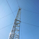
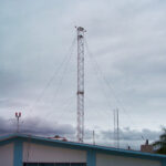
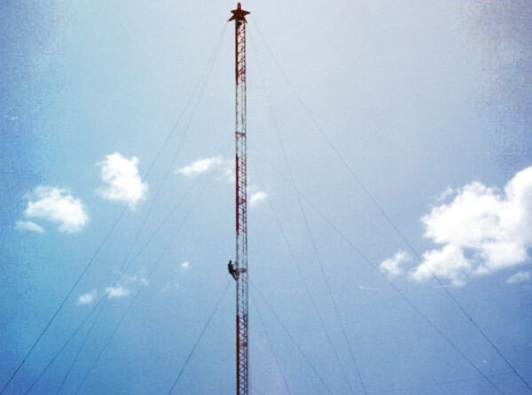
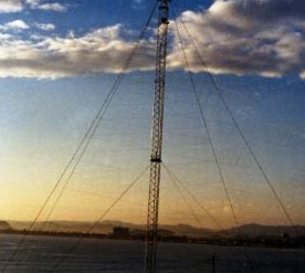
The SRQ-230C is a broadband, multimode, HF spiral antenna that is designed for rooftop or similar limited space applications where full duplex operation is desired on both short and medium range circuits simultaneously. Its relatively small size and multifunctional operation makes it ideally suited for rooftop or similar type installations.
Features:
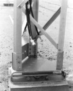
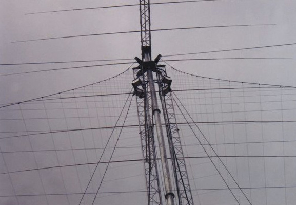
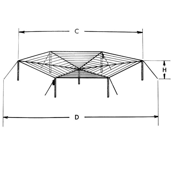
The antenna is a four arm equiangular spiral design that is wound on a pyramid structure formed by a center support tower and four catenaries. The base of the pyramid is a 40 ft. square with catenary anchors located at the corners of the square. The catenaries are dielectric with prepositioned element attachment clamps. The elements are constructed from jacketed cables that provide protection from the environment. The support tower is an all aluminum bolted structure.
Characteristics:
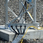
The antenna is fed with a four port hybrid and provides four independent radiation modes simultaneously. Two of the modes provide low angle, omnidirectional, conical radiation patterns. The other two modes provide axial radiation patterns with maximum radiation directed along the central axis of the pyramid. All four patterns are omnidirectional in azimuth. The two axial mode radiation patterns are used independently for transmit and receive on short range skywave circuits. The two conical mode radiation patterns are used independently for transmit and receive on the medium range circuits. The horizontally polarized conical mode is used for transmitting and the vertically polarized conical mode is used for receiving. The apex of the SRQ-230C spiral is directed toward the zenith; therefore the radiation patterns are essentially independent of the roof or ground except at the lower frequencies. This is important since many roofs do not have good reflective properties. Each input is isolated from all other inputs, typically in excess of 30 dB (installation dependent). Additionally, each axial mode input provides full 2 to 30 MHz bandwidth with input VSWR less than 2:1. The conical low angle mode inputs provide for 4 to 30 MHz bandwidth operation with an input VSWR less than 2:1 for the horizontally polarized transmit mode and less than 4:1 for the vertically polarized receive model. The antenna is protected under US Patent 5189434.
Optional Equipment:
Erection kit, obstruction lighting kit, roof mount anchor kit, ground mount anchor kit. Coaxial cable, connector adapters and mating adapters.
Spec Sheet
|
SPECIFICATIONS |
PERFORMANCE |
|---|---|
| Power, kW | 1 kW avg and 2 kW PEP |
| Wind | 100 MPH (87 Knots) |
| Input Connector | Type “N” |
| Number of Ports (simultaneous) Medium Range | 2 |
| Number of Ports (simultaneous) Short Range | 2 |
| VSWR, Mode 1 High Angle | 2:1 |
| VSWR, Mode 3 Long Angle, Horizontal | 2:1 |
| VSWR, Mode 4 High Angle | 2:1 |
| Frequency Range, Short | 2-30 MHz |
| VSWR, Mode 2 Low Angle, Veritcal | 4:1 |
| Installation Area | 40 Feet by 40 Feet (12.2 Meters by 12.2 Meters) |
| Frequency Range, Medium | 4-30 MHz |
| Height | 45 Feet (13.72 Meters) |
| input Impedance | 50 Ohms Unbalanced |
| Directive Gain | 7 dBi Nominal |
| Polarization | Elliptical |
| Azimuth Radiation Pattern | Omnidirectional, +/- 1.5 dB |
| Elevation Pattern | Variable with Mode and Frequency |
Related products

LPV-1606 HF Long Range LP Dipole Antenna x4 Array 3-30 MHz 200 ft
 View Product Specs PDF | Request Quote
Not finding what you're looking for? We can custom-build antennas to your exact specifications.
Contact us here or call 1-940-325-3301 for more information.
View Product Specs PDF | Request Quote
Not finding what you're looking for? We can custom-build antennas to your exact specifications.
Contact us here or call 1-940-325-3301 for more information.
LPV-1215 HF Long Range LP Dipole Antenna 7-30 MHz 12 dBi 84 ft
LPV-1208 HF Long Range LP Dipole Antenna 4-30 MHz 12 dBi 160 ft
View Product Specs PDF | Request Quote
Not finding what you're looking for? We can custom-build antennas to your exact specifications.
Contact us here or call 1-940-325-3301 for more information. 
MAS-5 HF Multiport Antenna w/RLPA 2-30×2/4-30×3 MHz 106 ft
- Frequency Range: 2-30, 4-30, 2-30, 2-30, 4-30
- Gain: 7, 7, 7, 7, 9-12 dBi
- VSWR: 2.0:1 typical, 4.0:1 Max, 2.5:1 typical, 2.0:1 typical, 2.0:1 typical, 2.0:1 typical
- Polarization: Elliptical, Vertical, Horizontal, Elliptical, Horizontal
- Pattern: Omni, Omni, Omni, Omni, Directional
- Size: 106' H x 100' L x 100' W
SPQ-230 HF Four Arm Multiport Spiral Antenna 2-30×4 MHz 160 ft
SPR-330 HF Log Periodic Spiral Antenna 3-30 MHz 5 dBi Omni
View Product Specs PDF | Request Quote
Not finding what you're looking for? We can custom-build antennas to your exact specifications.
Contact us here or call 1-940-325-3301 for more information. 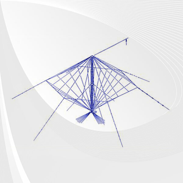
VOBA-II HF Broadband Antenna 2.5-30 MHz 2 dBi Omni
View Product Specs PDF | Request Quote
Not finding what you're looking for? We can custom-build antennas to your exact specifications.
Contact us here or call 1-940-325-3301 for more information.
VOBA-I HF Broadband Antenna 2-30 MHz 2 dBi Omni
View Product Specs PDF | Request Quote
Not finding what you're looking for? We can custom-build antennas to your exact specifications.
Contact us here or call 1-940-325-3301 for more information.